How a battery becomes an outlet
The system overview, the electrical theory of DC vs AC, and the mechanism inside the inverter that bridges them.
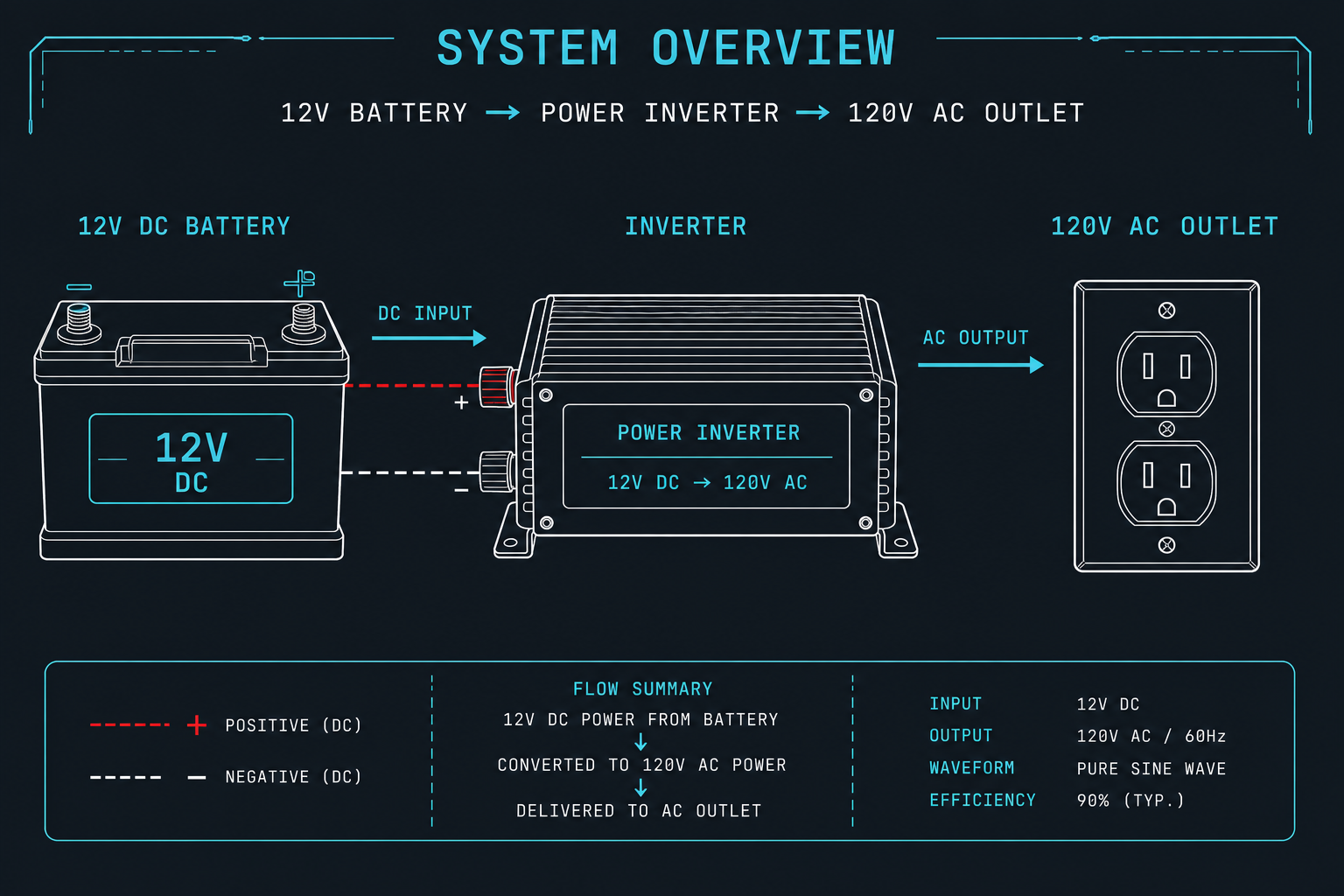
What a battery-powered outlet looks like
DC vs AC current — why an inverter is needed
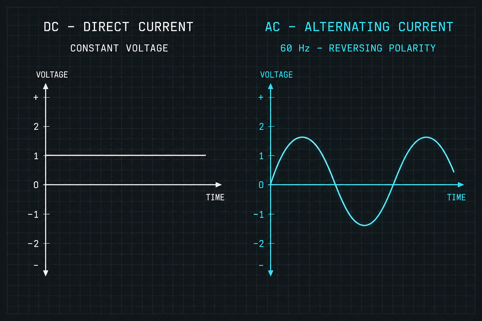
Batteries deliver direct current (DC) — a steady one-way flow of electrons from the negative terminal to the positive terminal. Wall outlets supply alternating current (AC) — voltage that swings positive and negative 60 times per second (60 Hz in North America, 50 Hz in most of the world). Cord-powered devices expect AC, so an inverter is the translator between them.
Chemistry only flows one way
A battery stores energy in a chemical reaction between two electrodes — an anode and a cathode — separated by an electrolyte. When the circuit closes, the reaction releases electrons at the anode that travel through the wire and return at the cathode. That reaction is inherently one-directional: electrons can only leave from the negative terminal.
You cannot make a battery output AC without external switching. The cell itself has no concept of "alternating" — it just has a fixed voltage between two terminals until it discharges. This is true for every chemistry: lead-acid, NiMH, lithium-ion, LiFePO4, and solid-state.
AC wins at long distances
The grid runs on AC because of one fact of physics: power lost in a wire equals current squared times resistance (P = I²R). Doubling the voltage halves the current for the same power, which cuts losses by a factor of four. To send electricity hundreds of miles, you want very high voltage and very low current.
Transformers can step voltage up and down cheaply and efficiently — but they only work with a changing magnetic field, which means they only work with AC. A power plant generates at ~25 kV, steps up to hundreds of kV for transmission, then steps back down to 120 V at your house. DC cannot do this with passive iron-and-copper transformers, which is why Edison's DC grid lost to Tesla and Westinghouse's AC grid in the 1890s.
Two systems, optimized for different jobs
AC is optimized for transmission — moving energy from a distant power plant to your wall. DC is optimized for storage — holding energy in a chemical cell you can carry. Most modern electronics (phones, laptops, LEDs, motors with variable speed drives) actually run on DC internally and convert AC back to DC inside the device. But the wall socket — the universal interface — stayed AC because that is what the grid delivers. An inverter exists to bridge a DC source to that AC interface so any cord-powered device can plug in.
How a power inverter works
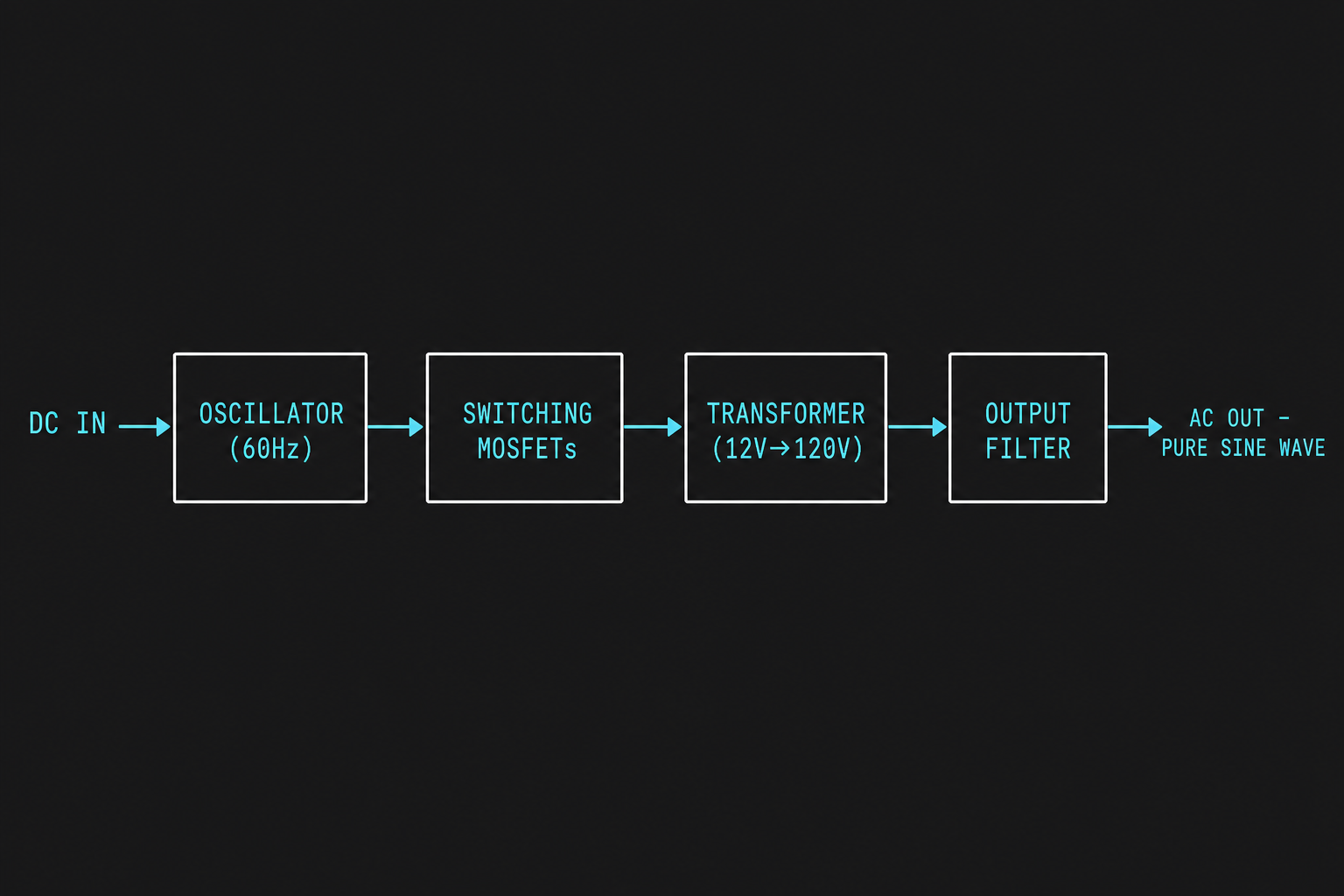
Inside every inverter, the same four-stage signal path turns a flat DC voltage into a clean 60 Hz sine wave. Cheap inverters cut corners on stages 1 and 4 and produce a "modified sine" (really a stepped square wave). Pure-sine inverters do all four stages carefully.
Generate the timing signal
A small chip (commonly an SG3525, EGS002, or a microcontroller like an STM32 or ATmega) produces a low-voltage logic-level waveform that tells the power stage when to switch. For a pure-sine output, this stage uses sinusoidal pulse-width modulation (SPWM): a high-frequency carrier (15–25 kHz) whose duty cycle is varied along a 60 Hz sine reference. The wider the pulse, the higher the instantaneous voltage the filter will reconstruct.
This stage also handles dead-time insertion (a few hundred nanoseconds where both high-side and low-side switches are off, to prevent shoot-through), feedback from the output for voltage regulation, and shutdown logic for overcurrent, overtemp, and undervoltage lockout.
Chop DC into alternating pulses
Four power MOSFETs (e.g. IRF3205 for 12 V, IRFP260 for higher buses) are arranged so that closing the diagonal pair Q1+Q4 sends current through the load in one direction, and closing Q2+Q3 reverses it. By alternating these pairs at the SPWM rate, the bridge produces a high-frequency train of ±Vbus pulses whose average follows the sine reference.
MOSFETs need gate drivers (IR2110, IR2184) because the high-side gate must be driven several volts above the bus rail — a bootstrap capacitor charges through a diode while the low-side switch is on, then floats up to drive the high-side gate. Heatsinking matters: each MOSFET dissipates conduction losses (I²·RDS(on)) plus switching losses proportional to frequency.
Step the voltage up
A 12 V battery cannot feed a 120 Vrms outlet directly — the peak of a 120 Vrms sine is ±170 V. Two architectures solve this. Low-frequency (LF) inverters use a heavy iron-core 60 Hz transformer (turns ratio about 1:14) on the H-bridge output; reliable, tolerates surge loads well, but bulky.
High-frequency (HF) inverters add a first stage that boosts DC to ~170 V using a small ferrite-core transformer at 50–100 kHz, then runs a second H-bridge directly at the high-voltage DC bus. Lighter and cheaper, but less surge-tolerant. Either way, the transformer also provides galvanic isolation between the battery and the AC side, which is a safety requirement for grounded outlets.
Smooth pulses into a sine wave
The H-bridge output is still a chopped pulse train. A low-pass filter — a series inductor (typically 1–5 mH on a powdered-iron toroid) and a parallel film capacitor (1–10 µF X2-rated) — averages the pulses. The cutoff frequency is set well above 60 Hz but well below the 20 kHz switching frequency, so the sine passes through and the carrier is rejected.
A feedback loop measures the actual output and adjusts the SPWM duty cycle in real time to keep the RMS voltage at 120 V regardless of load. The result is a clean sine wave with under 3% total harmonic distortion (THD) — indistinguishable from grid power for any device you plug in, including motors, medical equipment, and sensitive electronics that misbehave on modified-sine inverters.
Want to build one from scratch?
Now that you understand how a battery becomes an outlet, you can build one yourself. A complete step-by-step DIY guide — bill of materials, diagrams, safety, and bench testing — lives on its own page.
Go to Build Your Own→