Build your own portable AC outlet
A complete weekend-to-weeklong project: a 300 W pure-sine, 12 V LiFePO4 portable power station with one 120 V outlet, USB-C PD, MPPT solar input, and battery management.
What you're building
Budget roughly $250–$400 depending on the cell deal you find. This is a real working design, not a toy — but it requires comfort with soldering, basic electronics, and respect for high-voltage AC.
Lithium cells can vent flames if shorted or overcharged. The AC side carries 170 V peak and can kill you. Always fuse the battery, never work on the AC side while the inverter is powered, and test outdoors on a fire-safe surface during first power-up. If you have not soldered before, build a smaller 5 V USB power bank first.
Bill of materials
| Part | Spec | Qty |
|---|---|---|
| LiFePO4 cell | EVE LF105 / 3.2 V 105 Ah, grade A | 4 |
| BMS | JBD/Daly 4S 100 A LiFePO4 with Bluetooth | 1 |
| Inverter board | EGS002 SPWM controller + IR2110 drivers | 1 |
| Power MOSFETs | IRFP260N (low-side) / IRF3205 acceptable | 8 |
| Toroidal transformer | 12 V → 120 V, 500 VA | 1 |
| Output inductor | 3 mH, 5 A, powdered-iron toroid | 1 |
| X2 film capacitor | 2.2 µF / 275 VAC | 1 |
| DC bus capacitors | 4700 µF / 25 V low-ESR | 4 |
| DC-DC buck | 12 V → 5 V 3 A for control + USB-A | 1 |
| USB-C PD module | 20 V / 3 A trigger + protection | 1 |
| MPPT solar charge controller | Victron 75/15 or Renogy Wanderer 10 A | 1 |
| NEMA 5-15R outlet | Hospital-grade with built-in GFCI | 1 |
| DC fuse + holder | ANL 60 A on battery positive | 1 |
| Main contactor / switch | 60 A latching relay or rocker | 1 |
| Aluminum heatsink | 100 × 80 × 25 mm finned | 1 |
| 80 mm 12 V fan | Thermistor controlled | 1 |
| Enclosure | Pelican 1450 or equivalent ABS toolbox | 1 |
| Wiring | 8 AWG silicone (battery), 14 AWG (AC), 22 AWG (signal) | — |
Build process
Plan the system and confirm the power budget
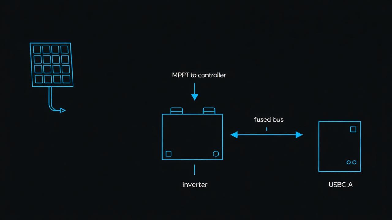
Decide what you need to run. A 300 W continuous / 600 W surge inverter handles laptops, fans, TVs, small power tools, and CPAP machines, but not a microwave or hair dryer. Four LiFePO4 cells in series give a nominal 12.8 V bus and about 1.3 kWh of energy — roughly 4 hours at full load, or a full day for laptop + lights.
Sketch the block diagram: solar → MPPT → battery ← BMS → fused bus → (inverter, 12 V→5 V buck, USB-C PD). Every load taps the fused bus, never the cells directly.
Build the LiFePO4 battery pack
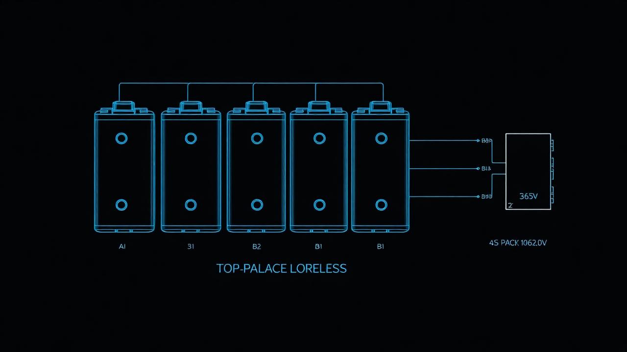
Top-balance all four cells before assembly: charge each one individually to exactly 3.65 V with a bench supply (CC then CV until current drops below 100 mA). Skipping this step is the #1 reason DIY packs fail early — once series-connected, cells can never re-balance themselves above the BMS's narrow balance current.
Compress the cells with end plates and threaded rod (LiFePO4 prismatics swell slightly when charged; manufacturer specs ~300 kgf). Connect in series with the supplied busbars torqued to spec (usually 6–8 N·m). Wire the BMS balance leads from B− up through B1, B2, B3, B+.
Attach the BMS between the pack negative and the system negative bus. The positive goes straight from pack+ through the ANL fuse to the bus. Never run the positive through the BMS unless your model is designed for it.
Assemble the inverter stage
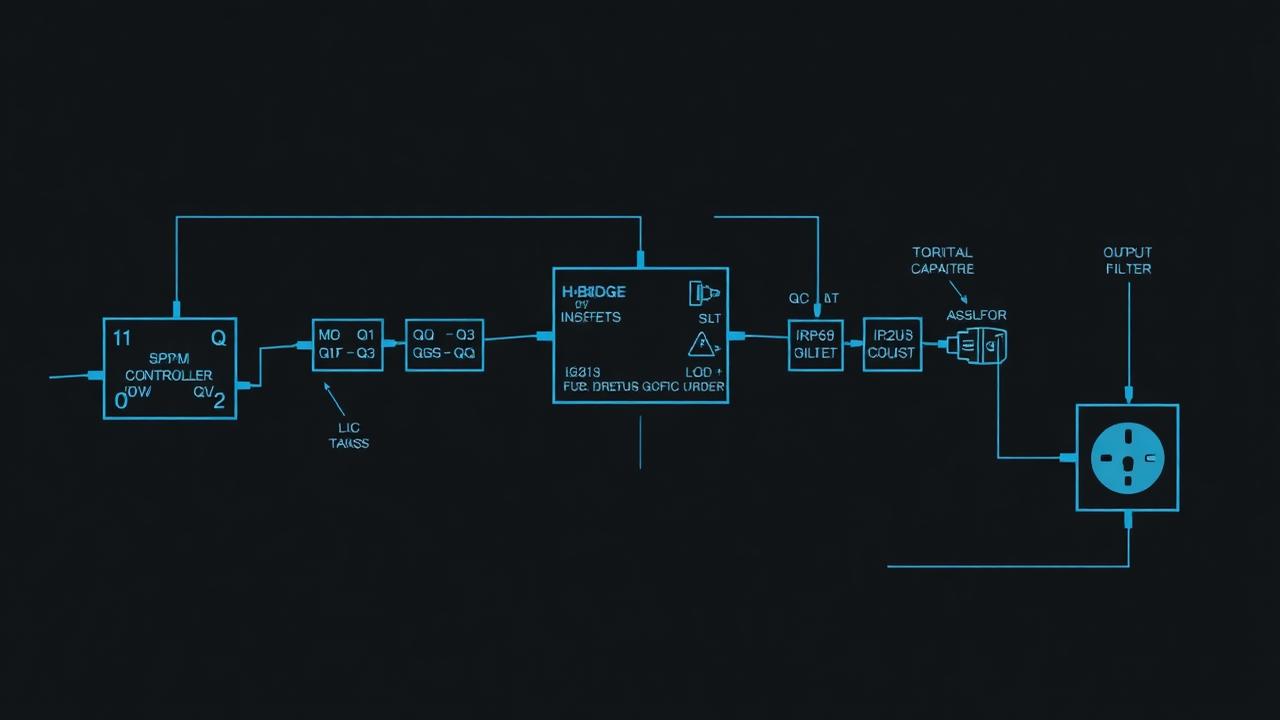
The EGS002 module is a drop-in SPWM controller that handles oscillator, SPWM generation, dead-time, soft-start, and protection. It outputs four gate signals (HO1, LO1, HO2, LO2) for the H-bridge. Mount it on a perfboard or a PCB cut to fit your enclosure.
Solder eight IRFP260N MOSFETs in two parallel banks of four (two per leg of the H-bridge) onto the heatsink with mica insulators and thermal paste. Each gate goes through a 22 Ω resistor to the corresponding gate-driver output. Connect the drains/sources per the H-bridge schematic, with the toroidal transformer's primary across the bridge midpoints.
Add the DC bus capacitors (4× 4700 µF) directly across the MOSFET supply rails with very short leads — long leads here cause ringing that destroys MOSFETs. The transformer secondary feeds the LC output filter (3 mH inductor in series, 2.2 µF X2 cap in parallel) and finally the GFCI outlet.
Wire the auxiliary outputs and charging
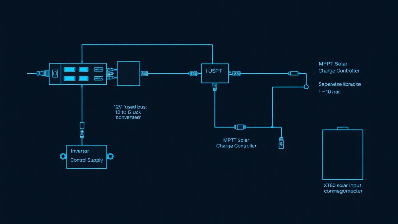
Tap the fused 12 V bus for: (a) the 12 V→5 V buck feeding a USB-A breakout for phone charging, (b) the USB-C PD module which negotiates 5/9/15/20 V for laptops, and (c) the inverter's own control supply. Each branch gets its own inline fuse sized to the wire (3 A for USB, 30 A for the inverter).
Wire the MPPT charge controller's battery terminals to the pack (through the BMS), and bring the solar input to an XT60 or MC4 panel-mount connector on the enclosure. Configure the MPPT for LiFePO4: 14.2 V absorption, 13.6 V float, no equalization. For wall charging, a 14.6 V / 10 A LiFePO4-specific power brick can plug into the same XT60.
Build the enclosure and mount everything
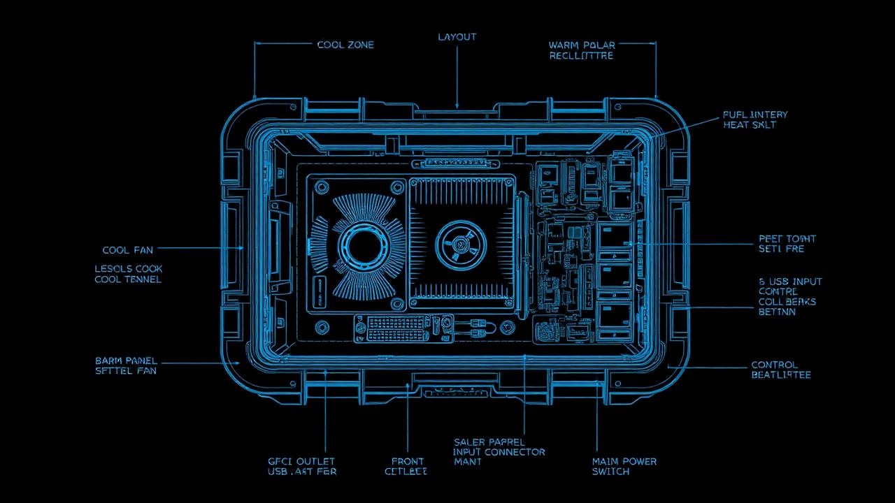
Lay out hot, warm, and cold zones: battery on one side, inverter + heatsink in the middle (with the 80 mm fan pulling air across the fins and out a vent), control electronics on the cool side. Cut panel holes for the GFCI outlet, USB ports, solar input, voltmeter, and main power switch.
Use 8 AWG silicone wire for everything between battery, fuse, contactor, and inverter. Crimp lugs with a hydraulic crimper (not pliers) and heat-shrink every joint. Keep AC-side wiring physically separated from low-voltage signal wiring; cross at right angles where they must meet.
First power-up and bench testing
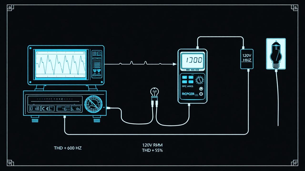
Before connecting the battery, do a continuity sanity check with a multimeter: no shorts from B+ to B−, no shorts from AC live to chassis. Then power the inverter from a current-limited bench supply at 12 V / 2 A. If the supply trips, you have a wiring fault — fix before connecting the real pack.
With a clean bring-up, scope the AC output: you should see a 60 Hz sine at ~170 V peak, 120 Vrms, with visible 20 kHz ripple on the rising edge that the LC filter mostly removes. Total harmonic distortion under load should measure below 5%. Test progressively: 25 W bulb → 100 W laptop charger → 300 W heat gun on low. Confirm the GFCI trips when you press its test button.
Calibrate, label, and field test
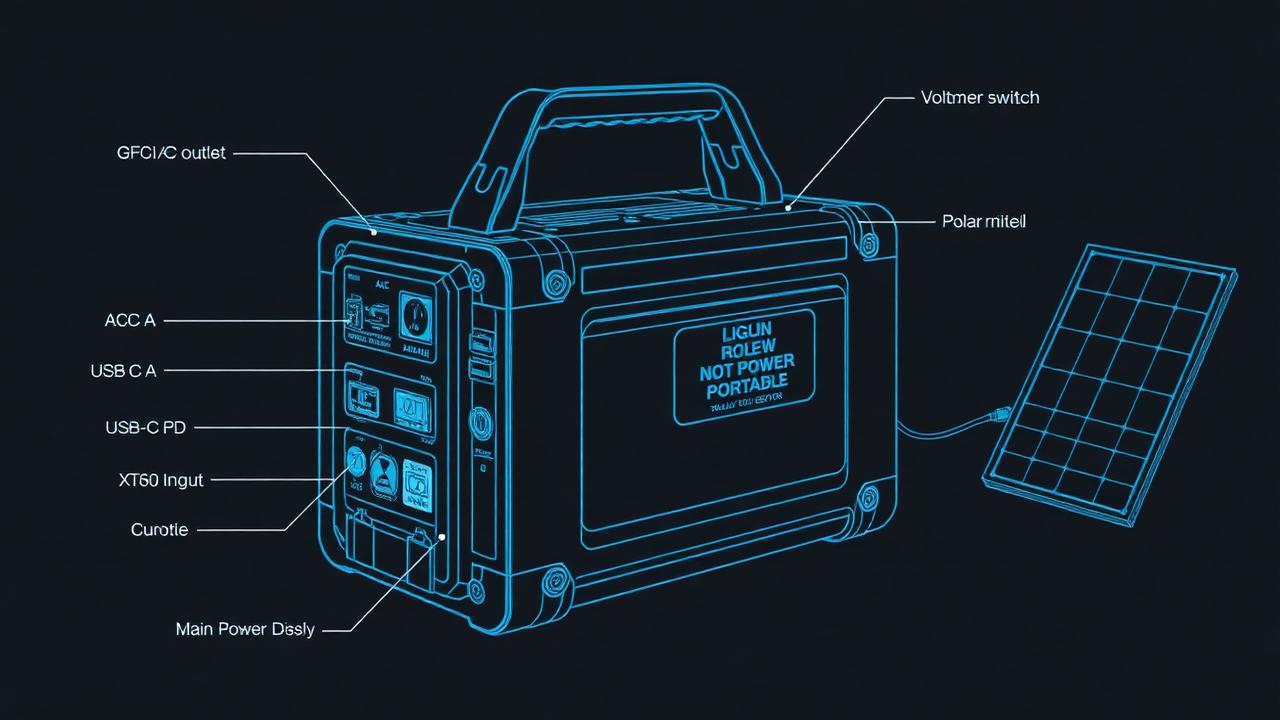
Trim the EGS002's output voltage pot for exactly 120 Vrms at half load. Verify the BMS cuts off at 2.5 V/cell discharge and 3.65 V/cell charge with a known load and charger. Label every external port, including a "DO NOT OPEN — LITHIUM" warning on the lid.
Run a real-world cycle: drain it from full to BMS cutoff with a 200 W load while logging temperature; the heatsink should stabilize below 60 °C with the fan running. Recharge from solar and from wall, confirming the MPPT reaches absorption and tapers correctly. You now have a portable AC outlet that works exactly like the commercial all-in-one stations covered elsewhere on this site — except you understand every electron in it.
- Swap to a 24 V or 48 V bus for higher inverter wattage with thinner wire.
- Add an ESP32 + INA226 for Wi-Fi telemetry of voltage, current, and SoC.
- Replace the EGS002 with a microcontroller running your own SPWM firmware for learning — STM32 timer-based PWM is the canonical project.
- Add a transfer switch so the unit can pass grid power through when plugged in and seamlessly invert when unplugged (true UPS behavior).